
1
2
3
4
5
6
7
8
9
10
11
12
13
14
15
16
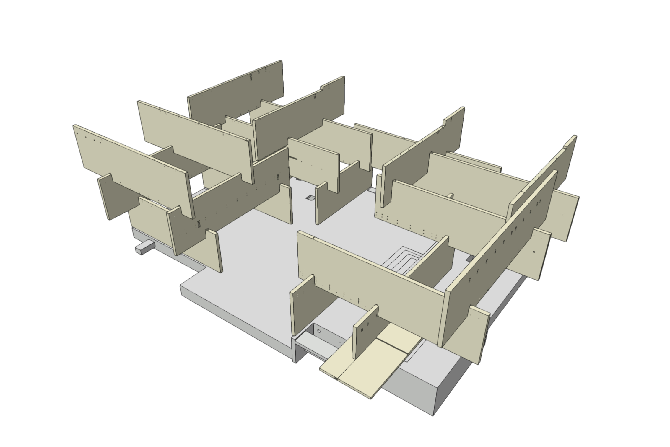
17. BIM Model 1
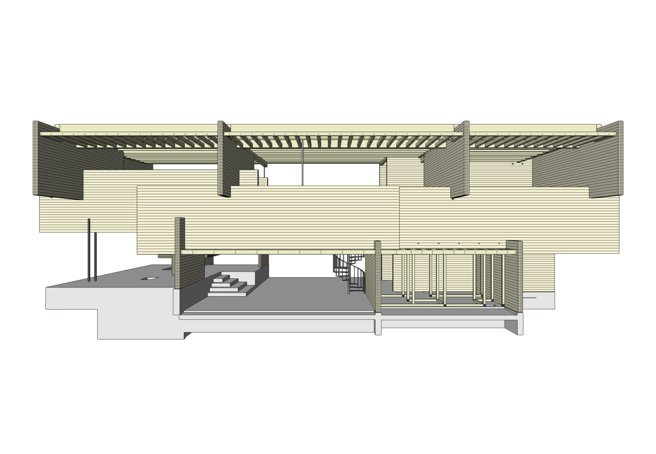
18. BIM Model 2
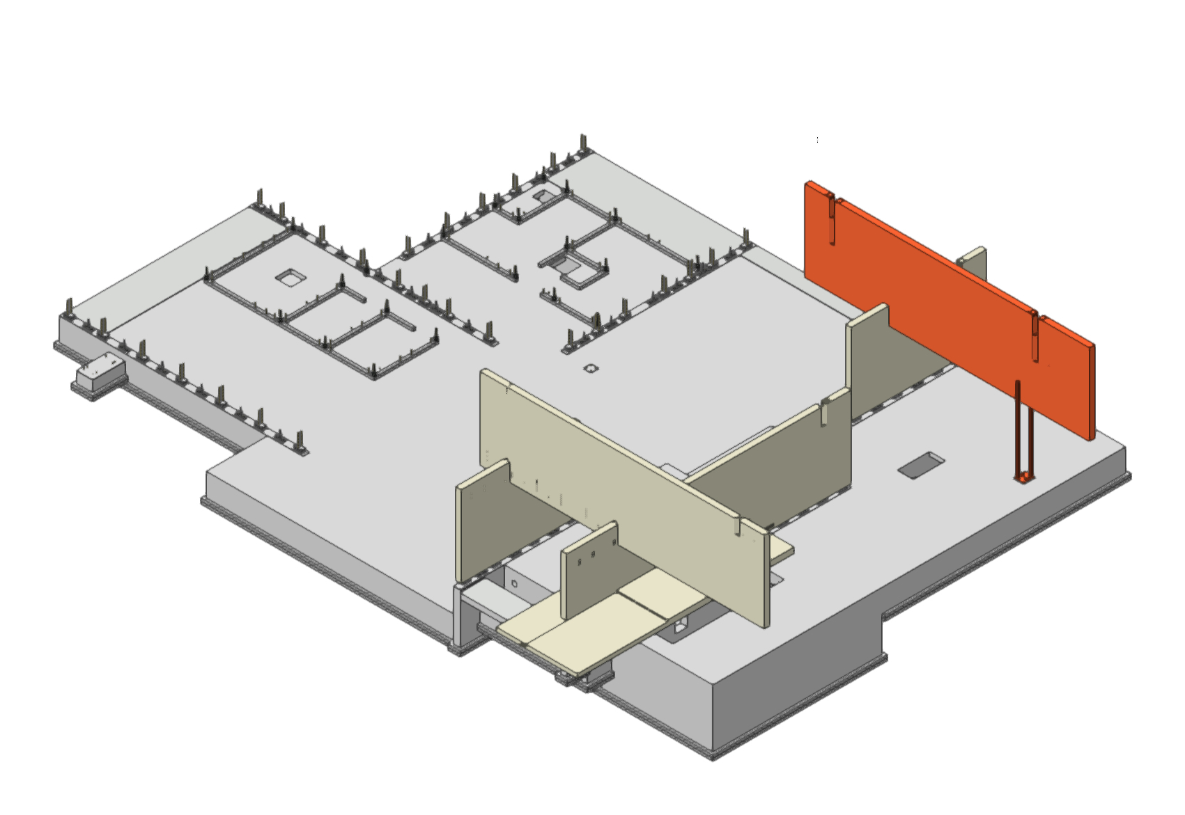
19. Construction procedure verification with BIM model 1
20. Construction procedure verification with BIM model 2
21. Construction procedure verification with BIM model 3
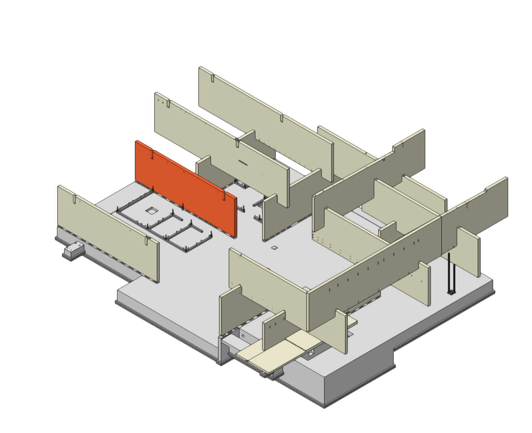
22. Interference check by BIM model 1
23. Interference check by BIM model 2
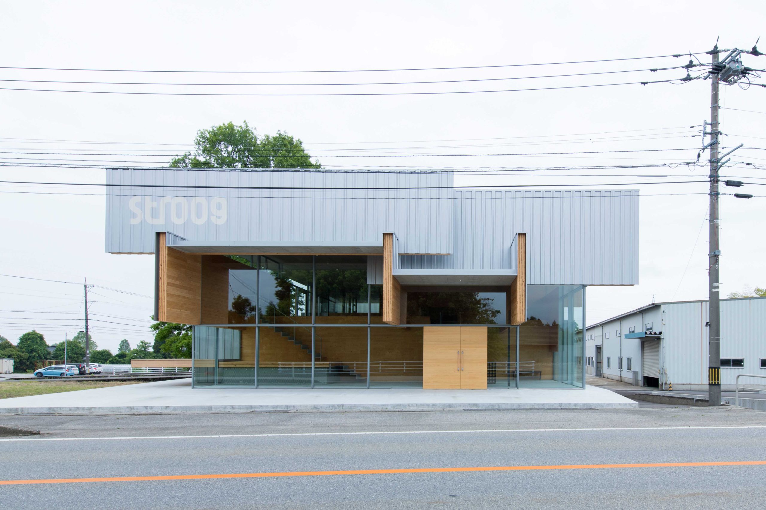
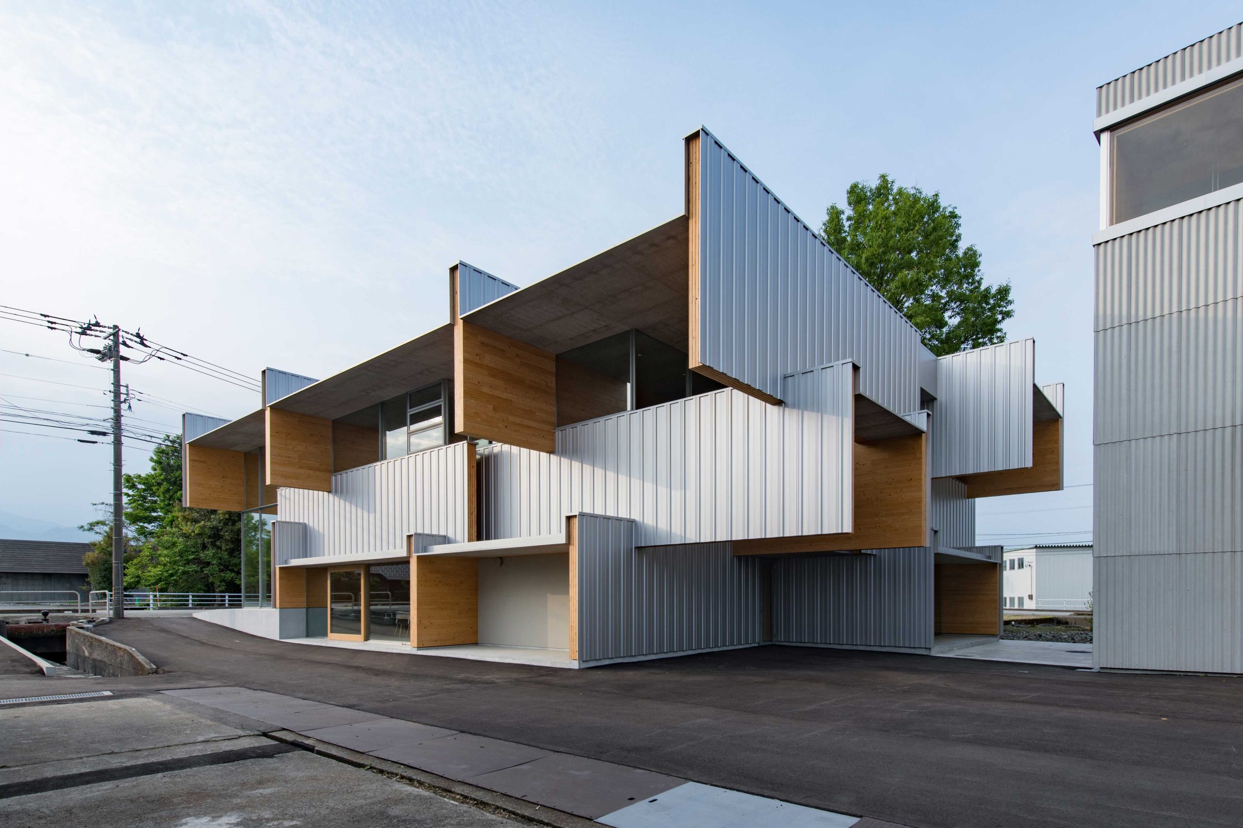
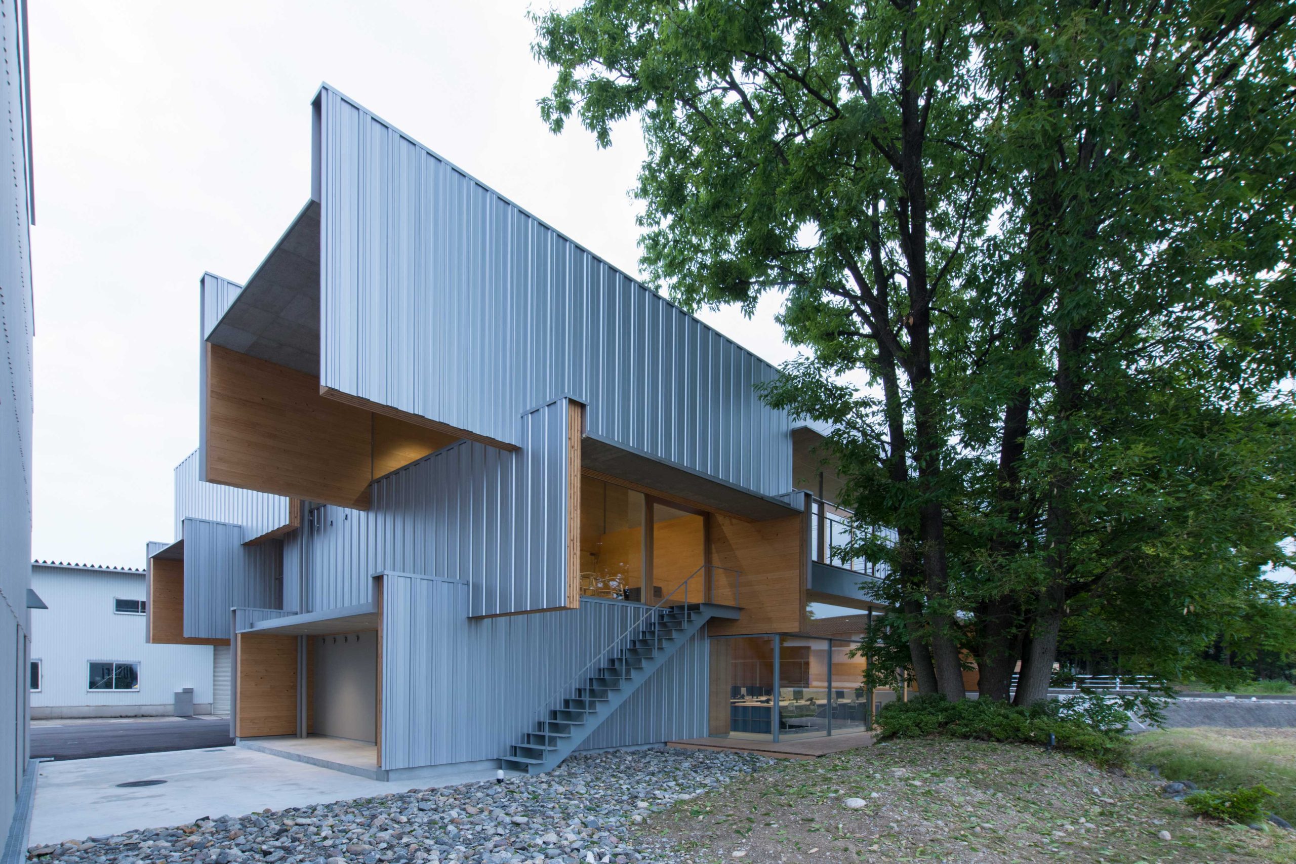
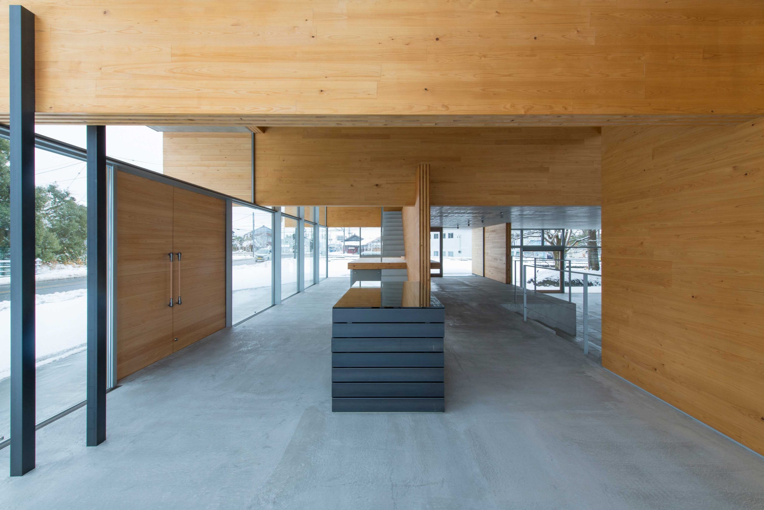
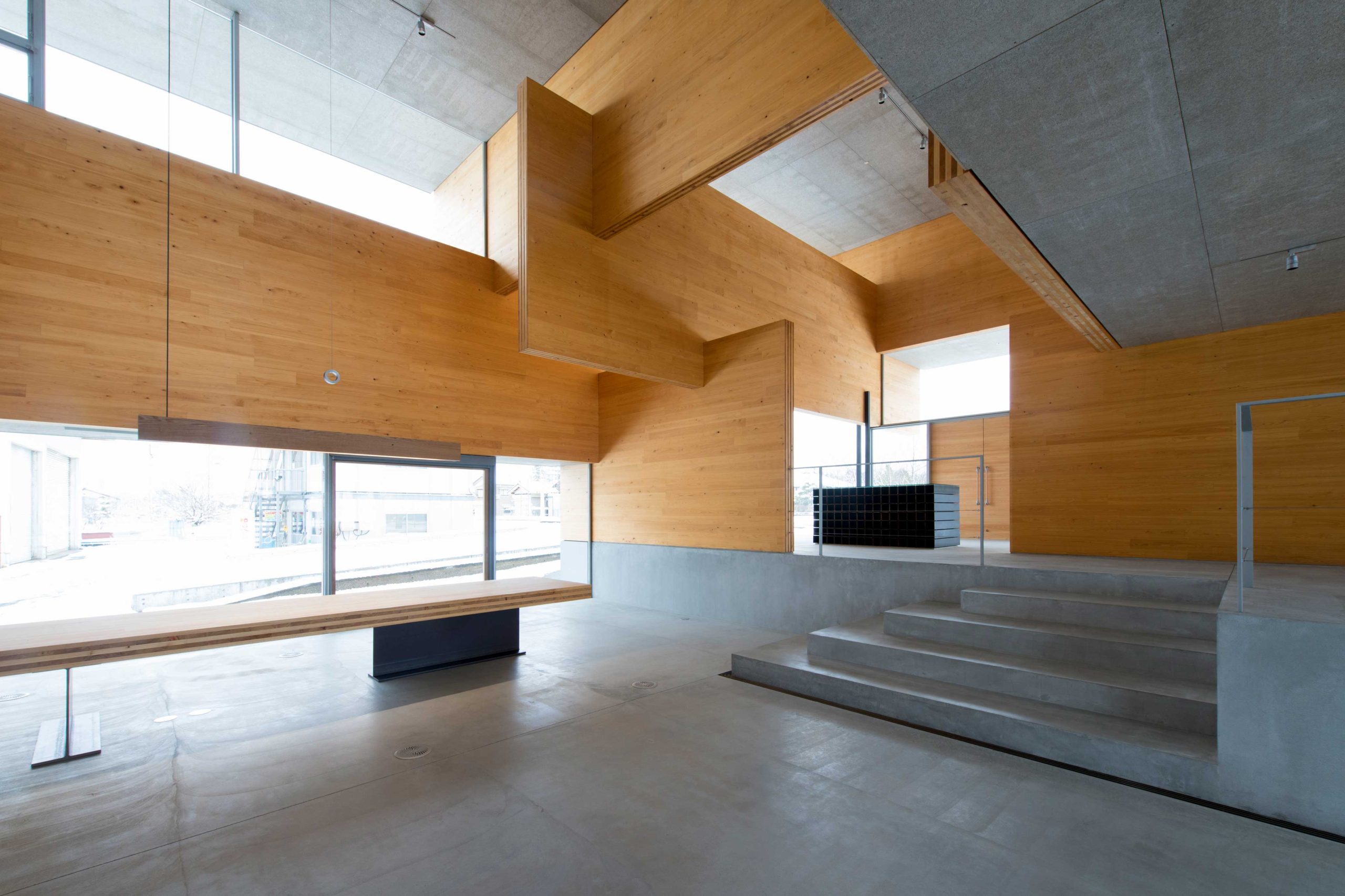
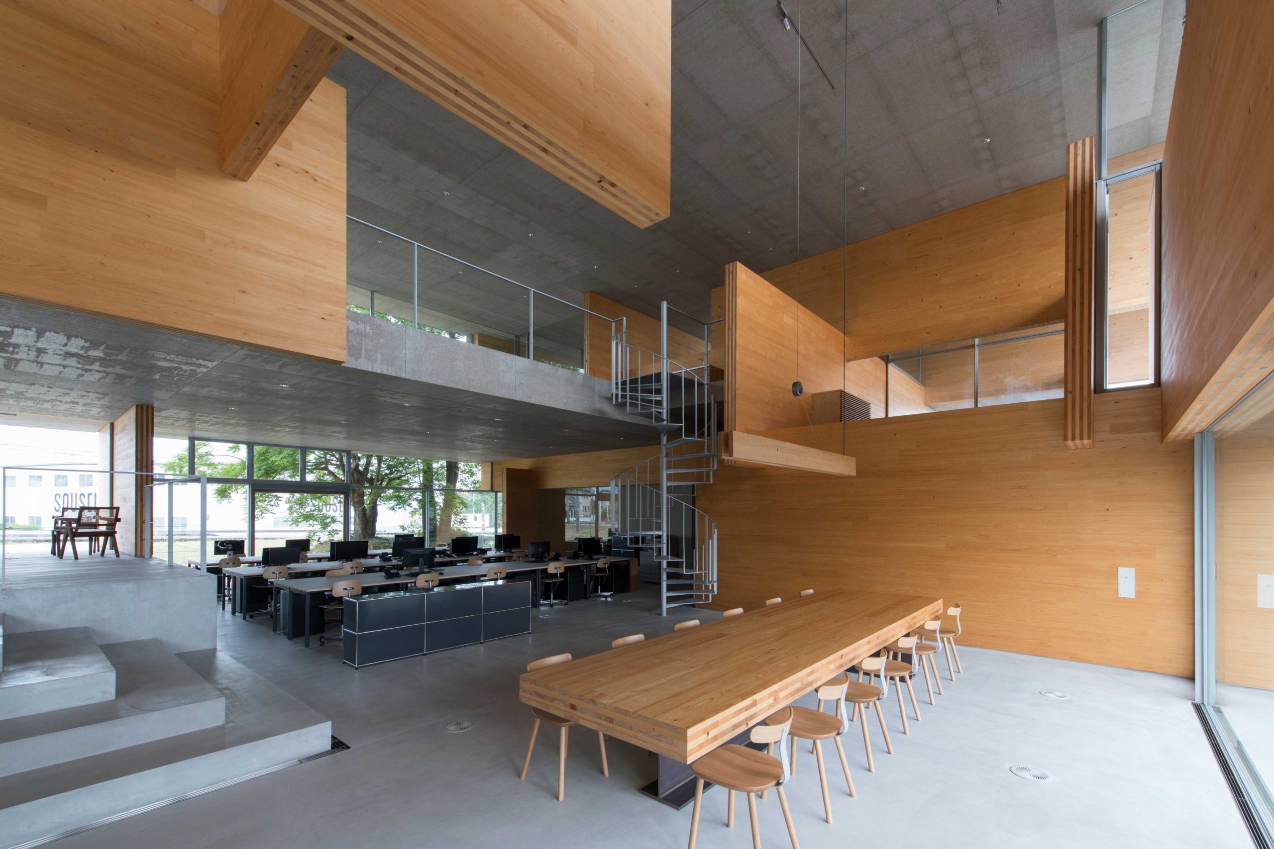
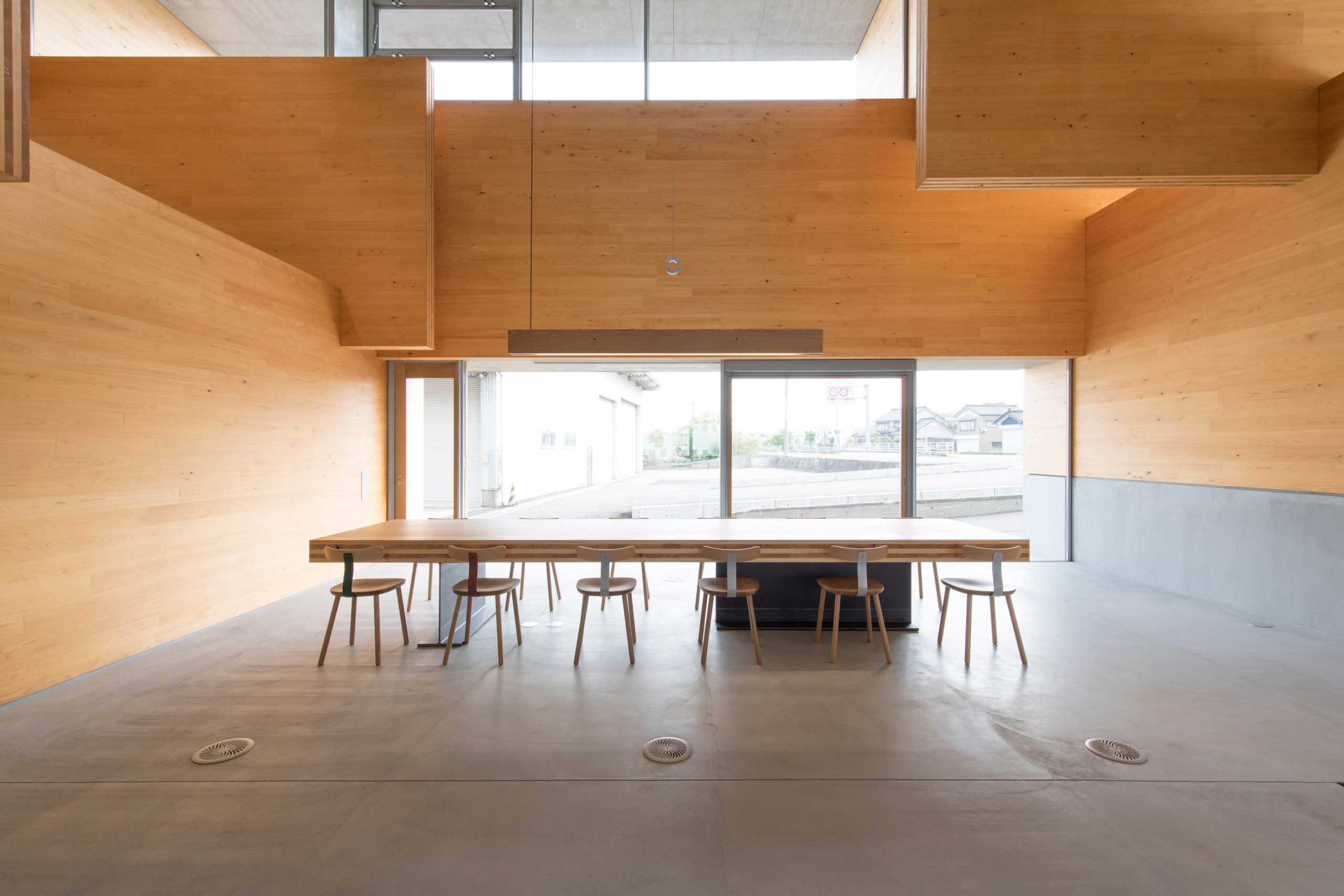
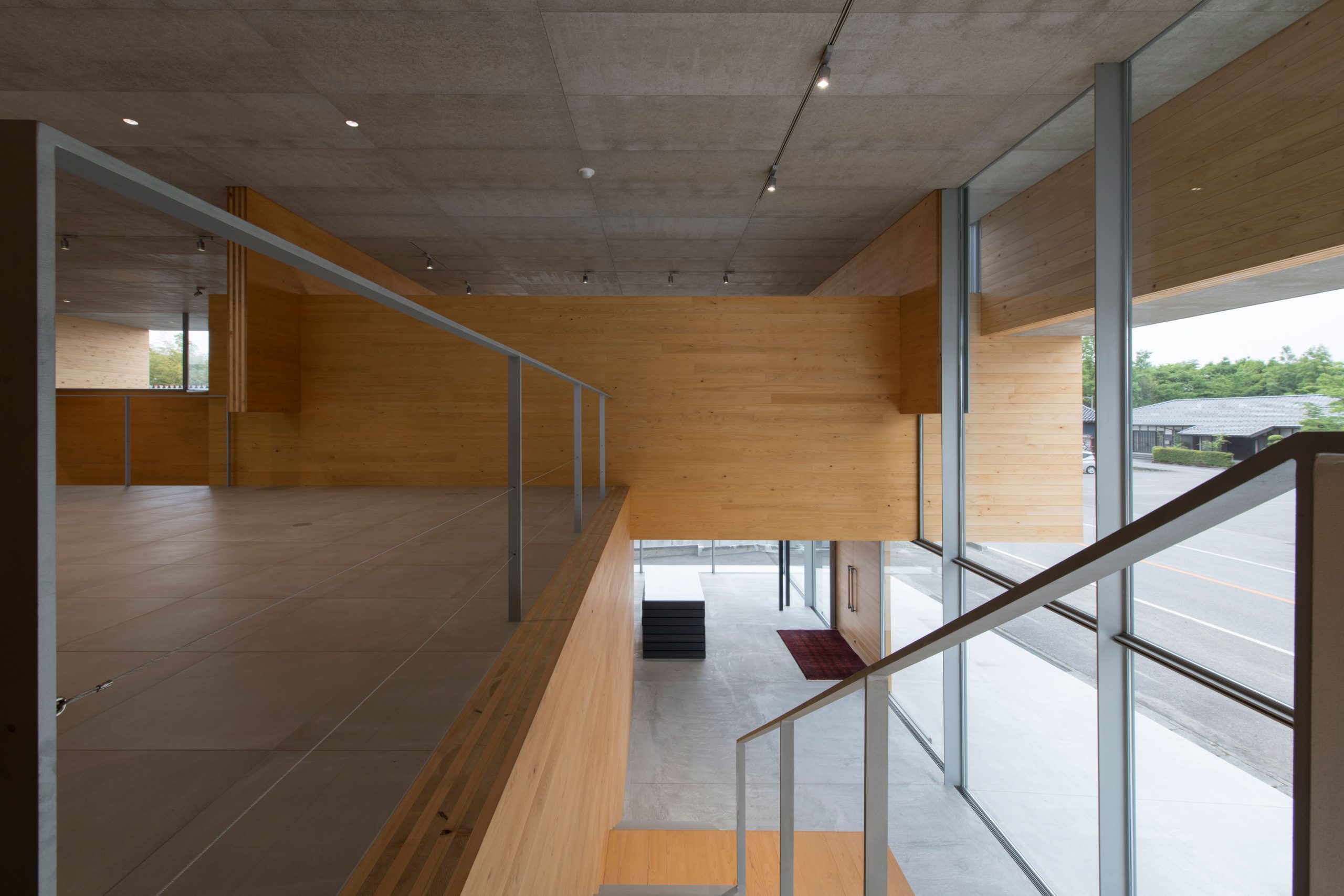
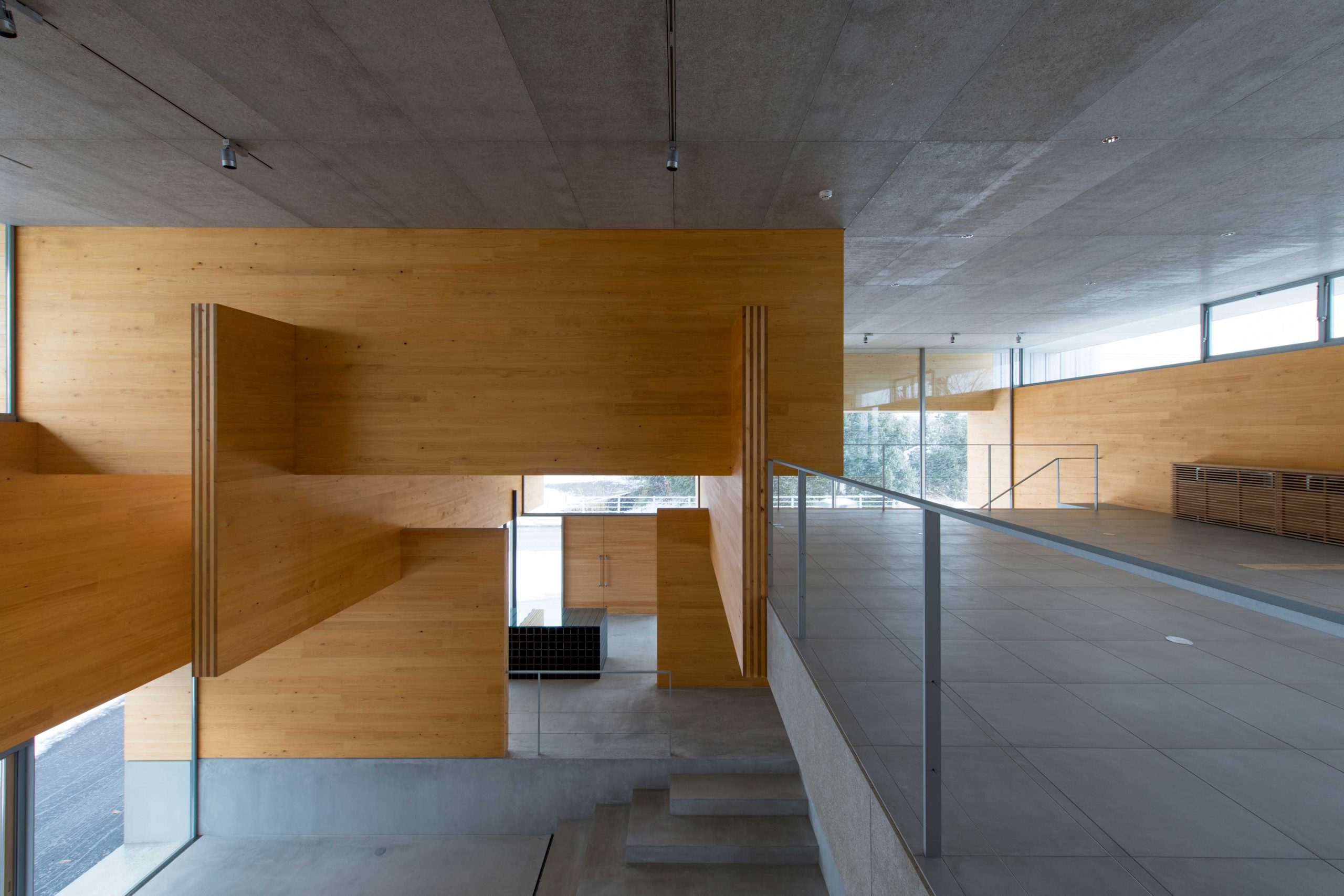
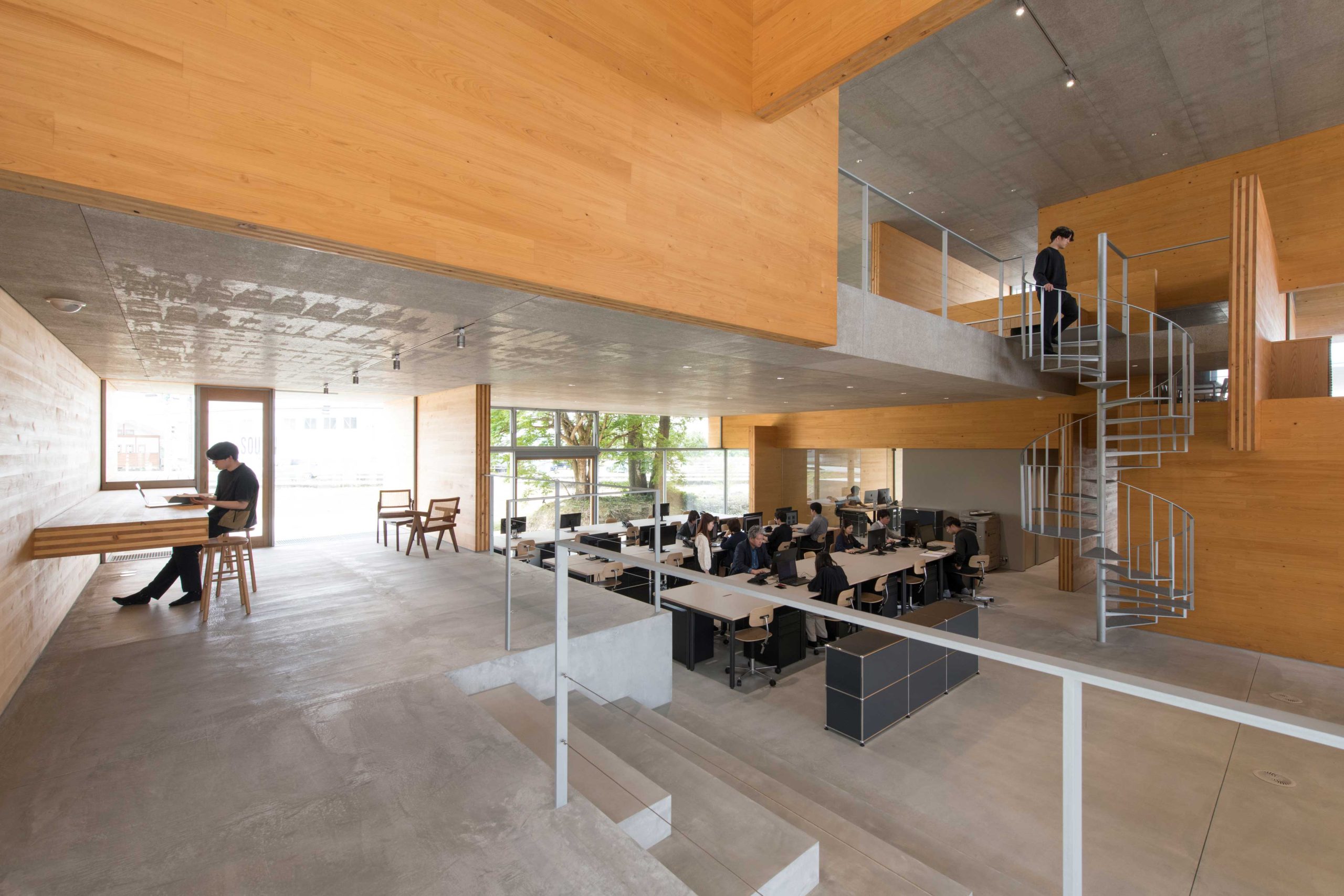
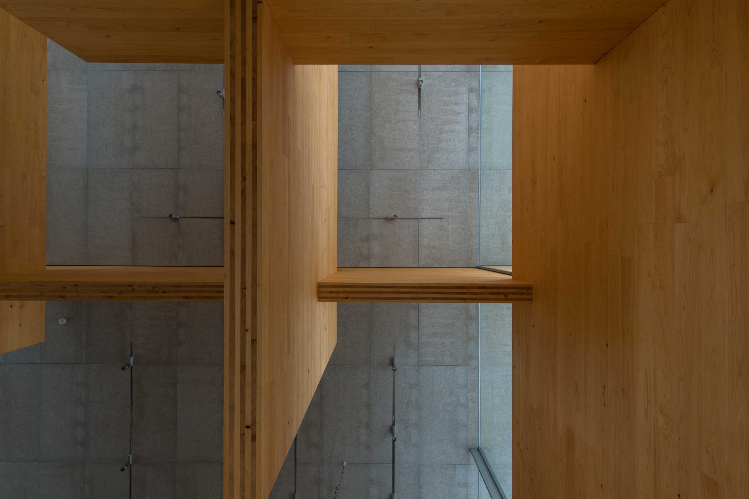
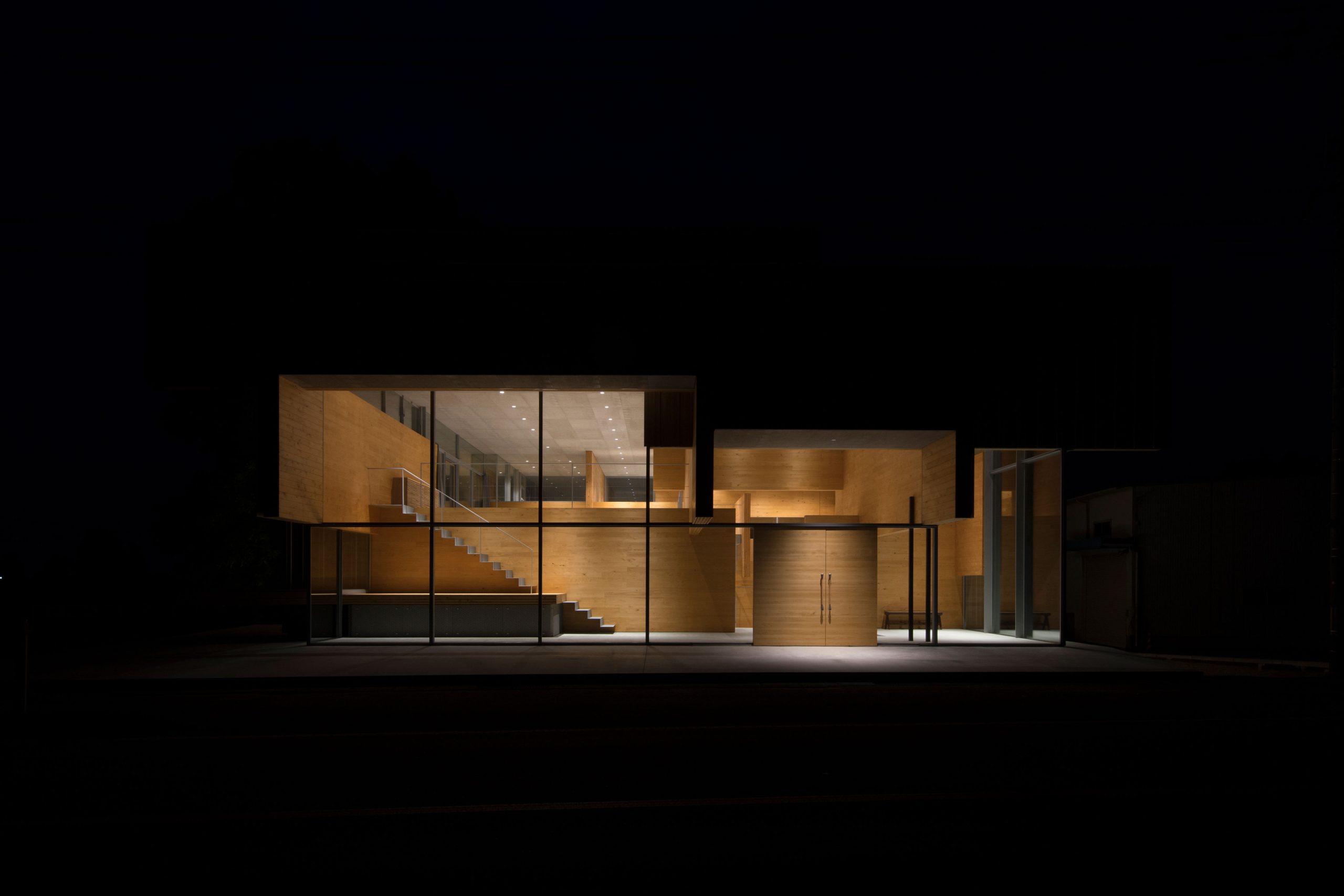
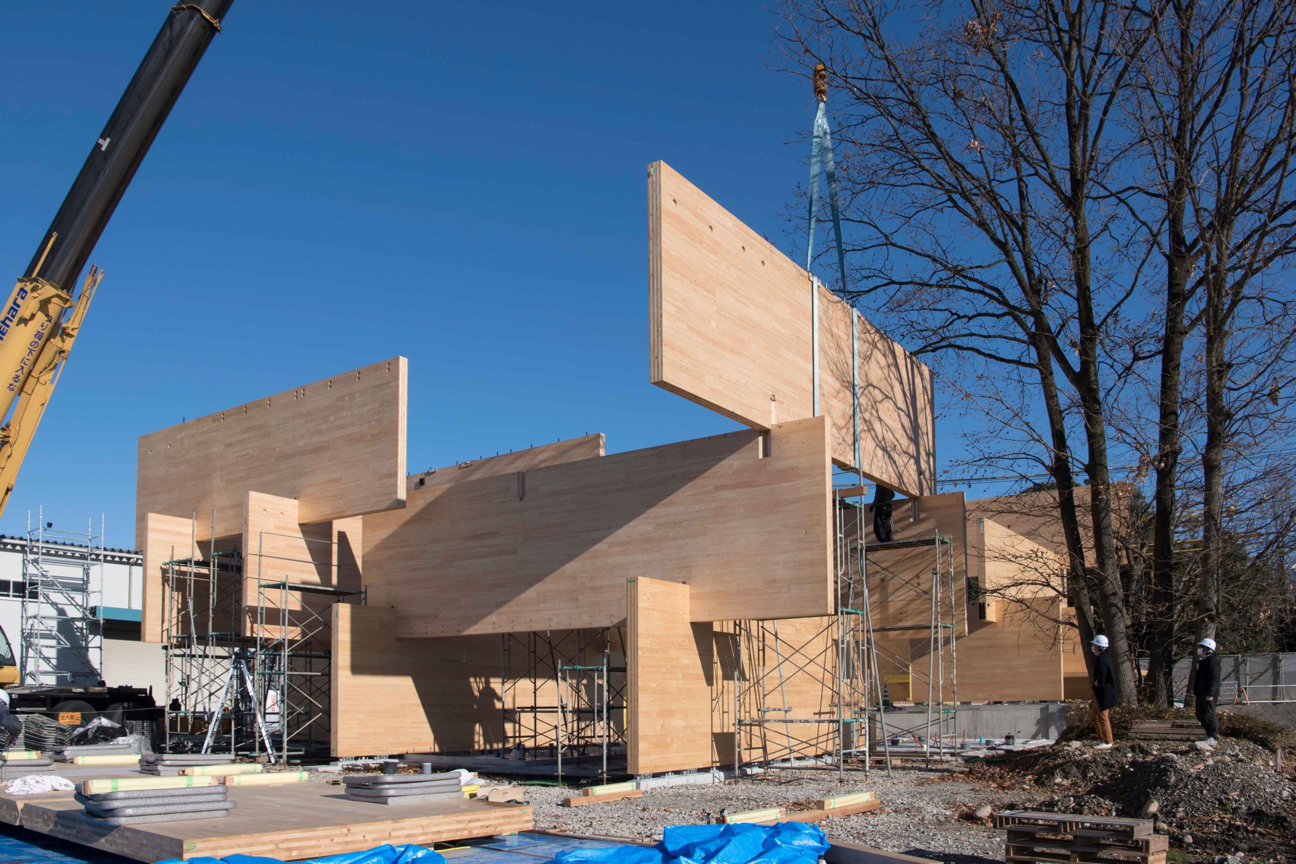
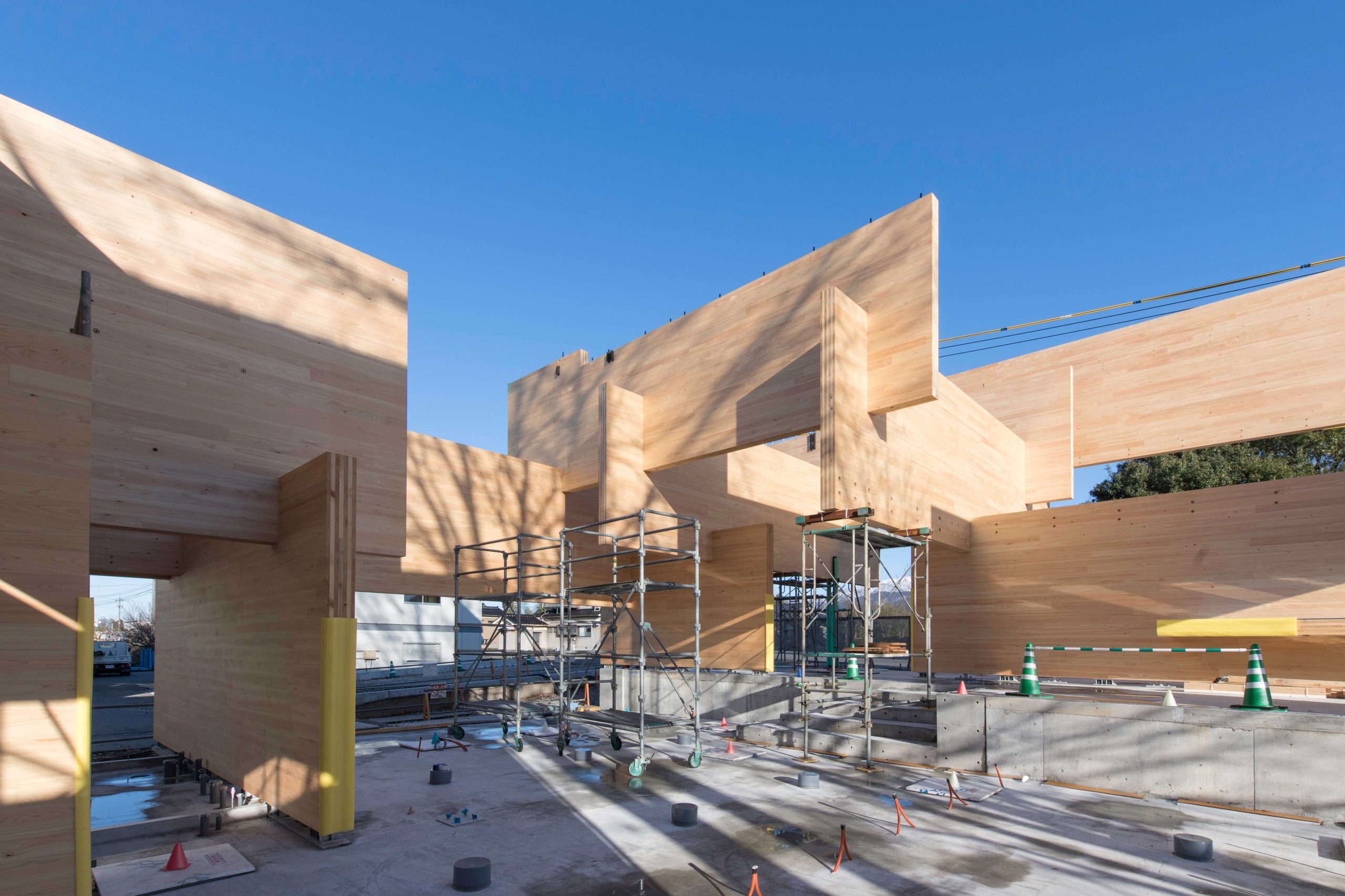
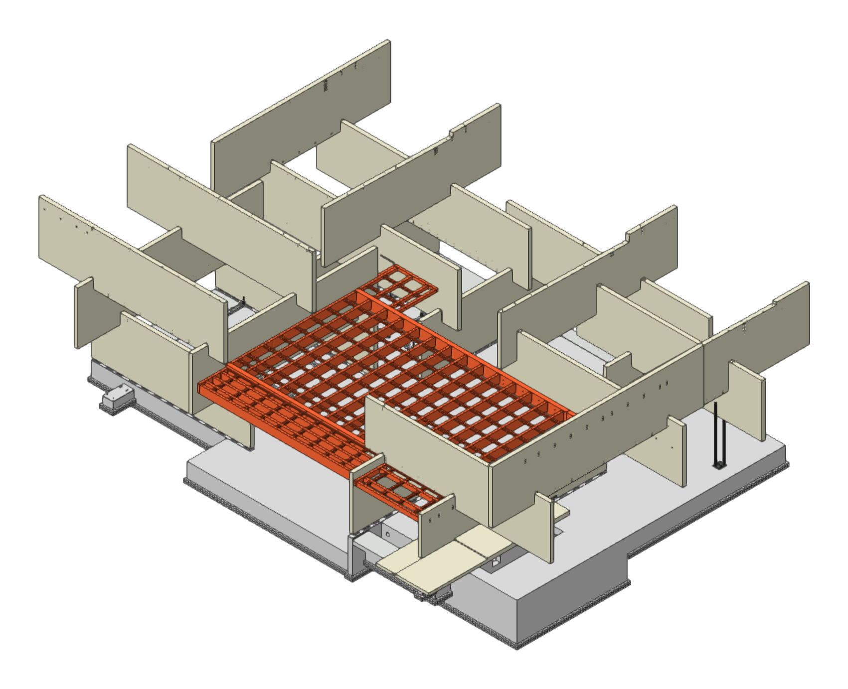
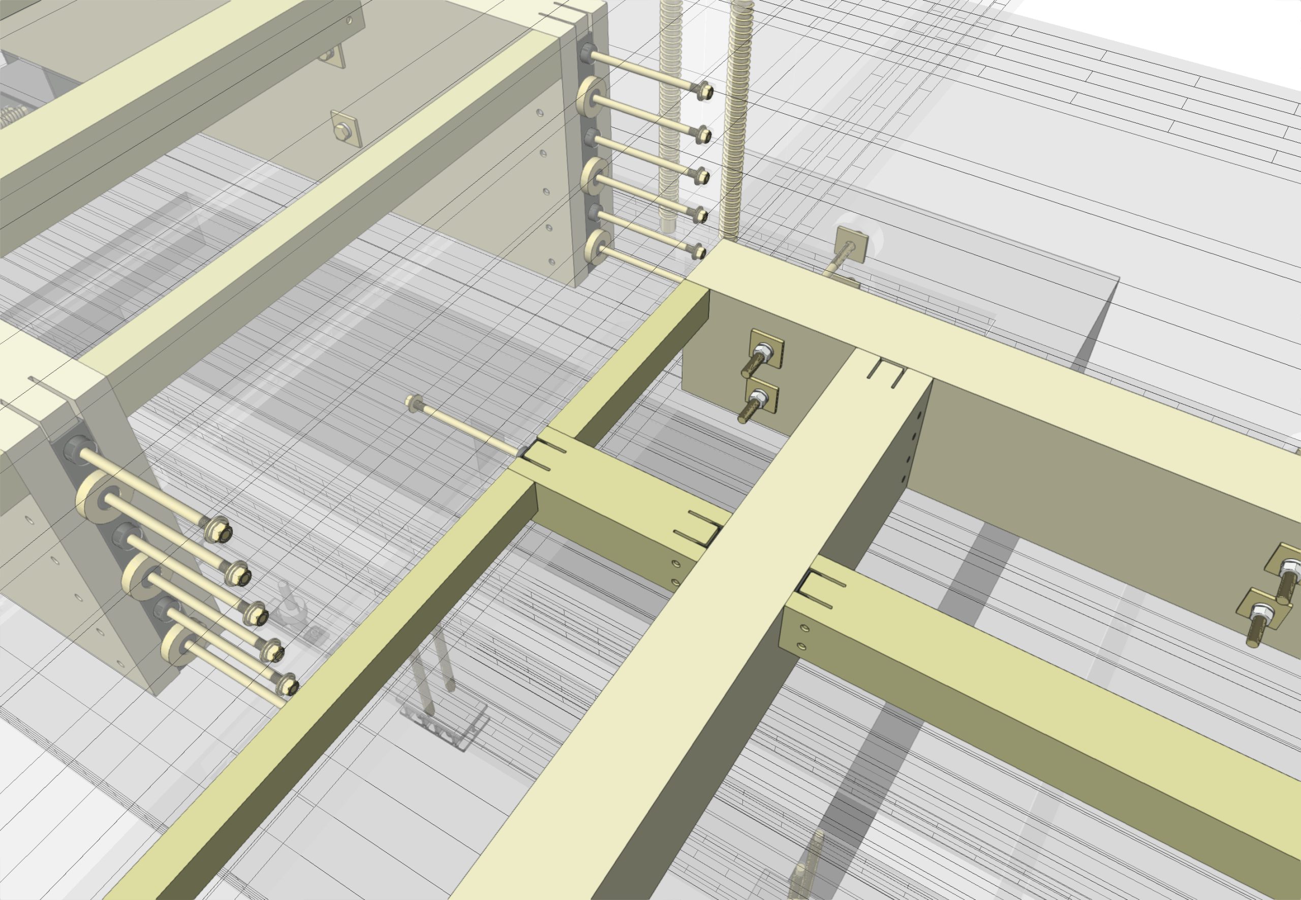
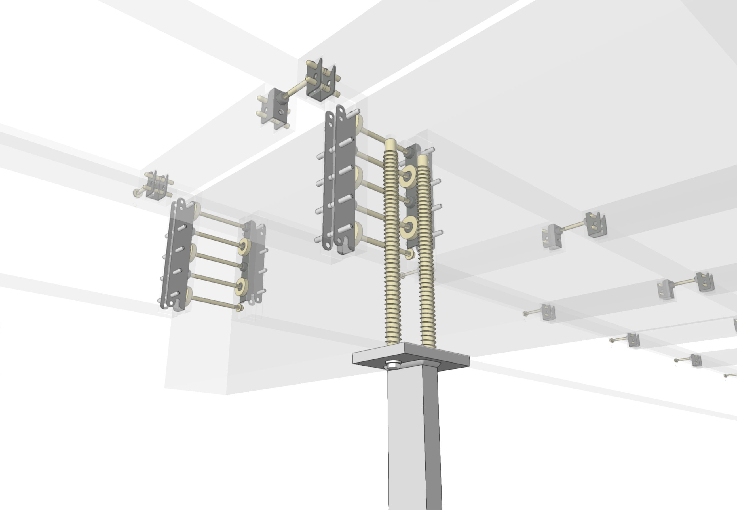
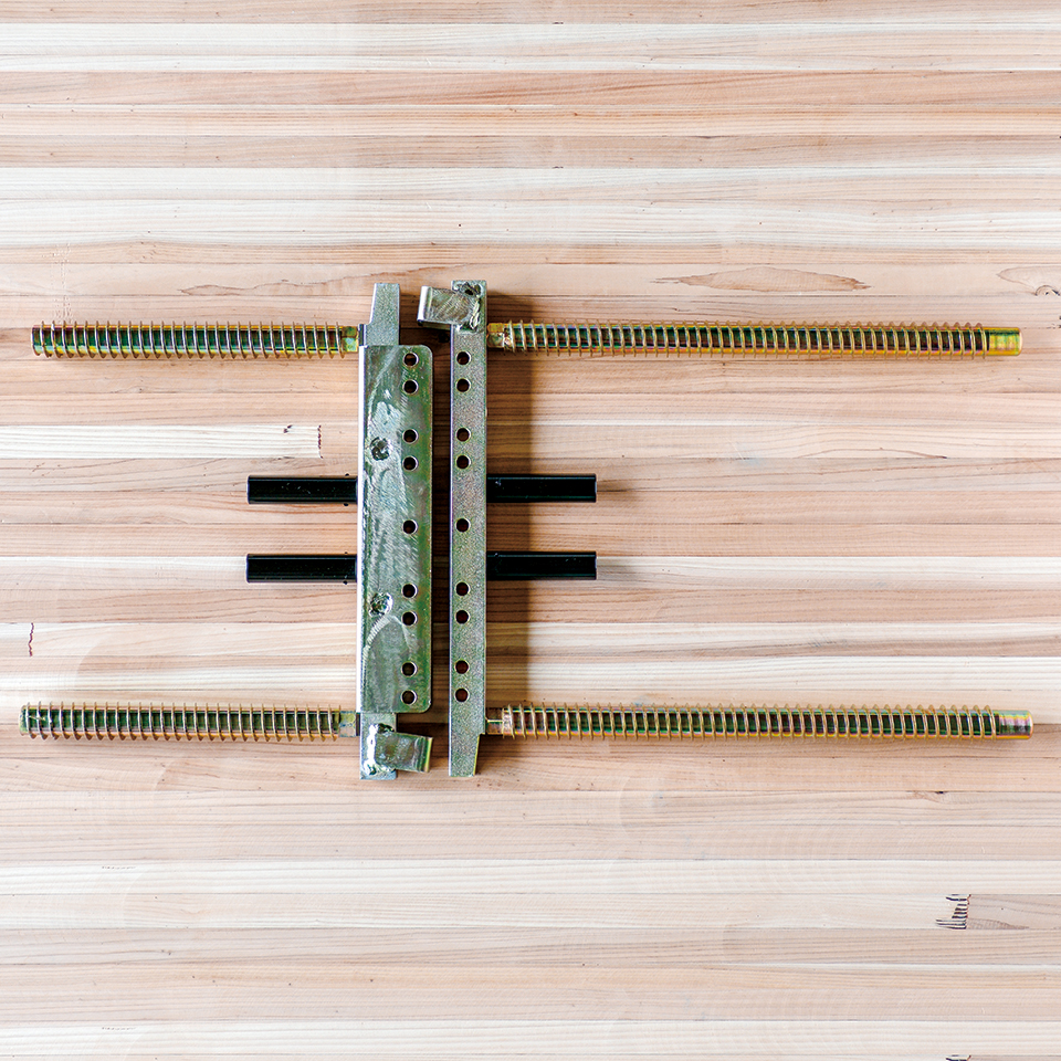
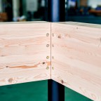
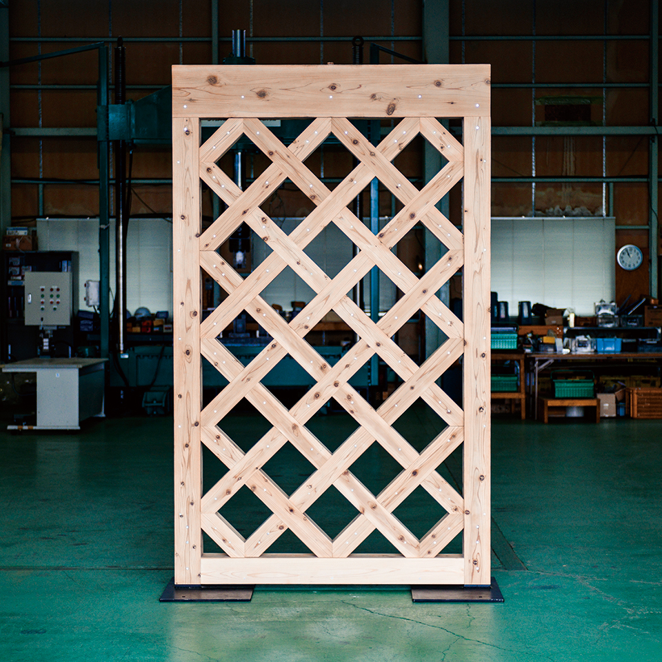
This is an office realized with a new and free building system that makes the most of CLT. The CLT panels, 210 mm thick, 3,000 mm wide, and 4,500 to 12,000 mm long, are cut at desired locations, fitted together in a well-girder shape, and assembled in a knock-down style. The joints between the CLT panels, which are orthogonal to each other at the top and bottom, are notched at 45 degrees to each other, maximizing the resistance of the fitted joints and enabling a free spatial configuration. The newly developed CLT connectors are used in this mating joint, and Stroog.LSB suppresses the rotational behavior of the entire panel in addition to moment resistance.
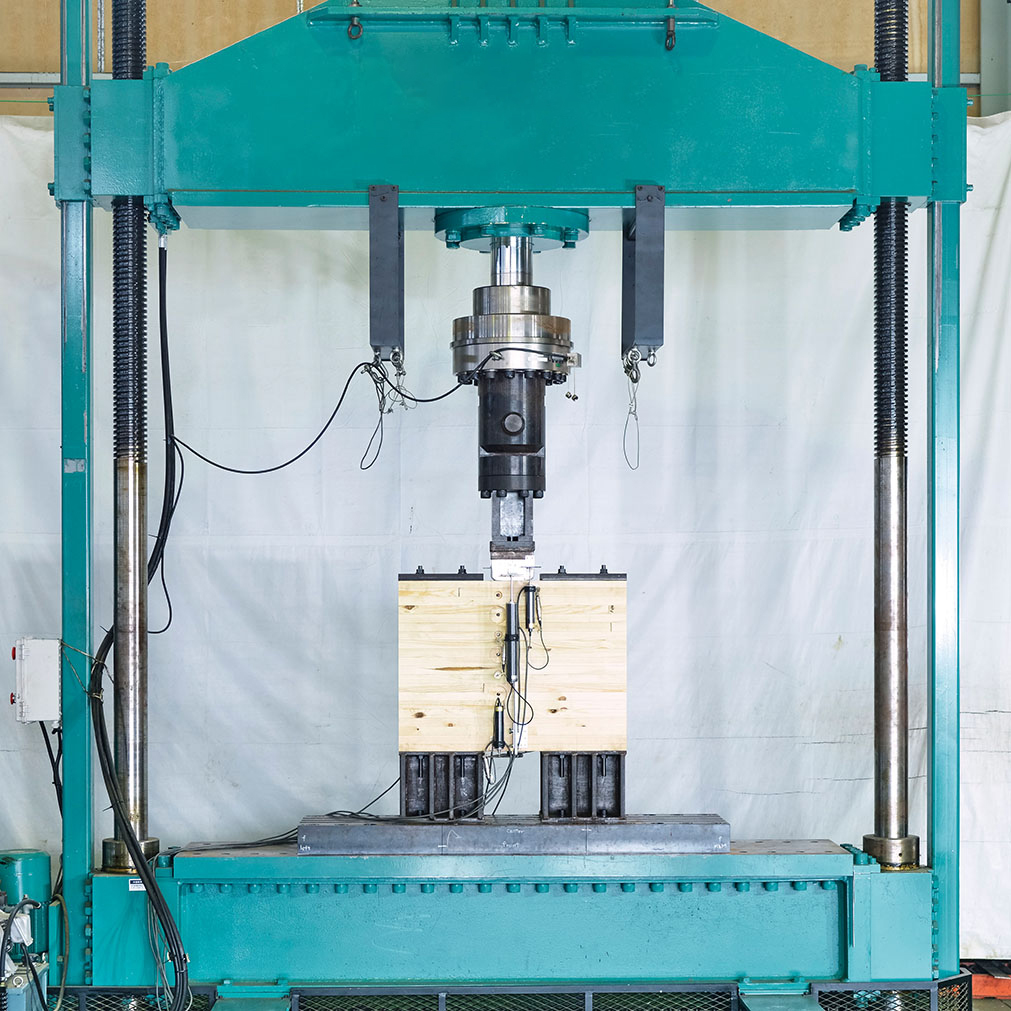
Because of new building systems, strength tests were conducted with Stroog.test as necessary to develop new connectors and to reflect them in structural calculations. Shear and weak-axis bending tests were conducted on the CLT legs, and bending tests were conducted on the CLT chamfer orthogonal sections, depending on the interlocking depth (large, medium, or small).
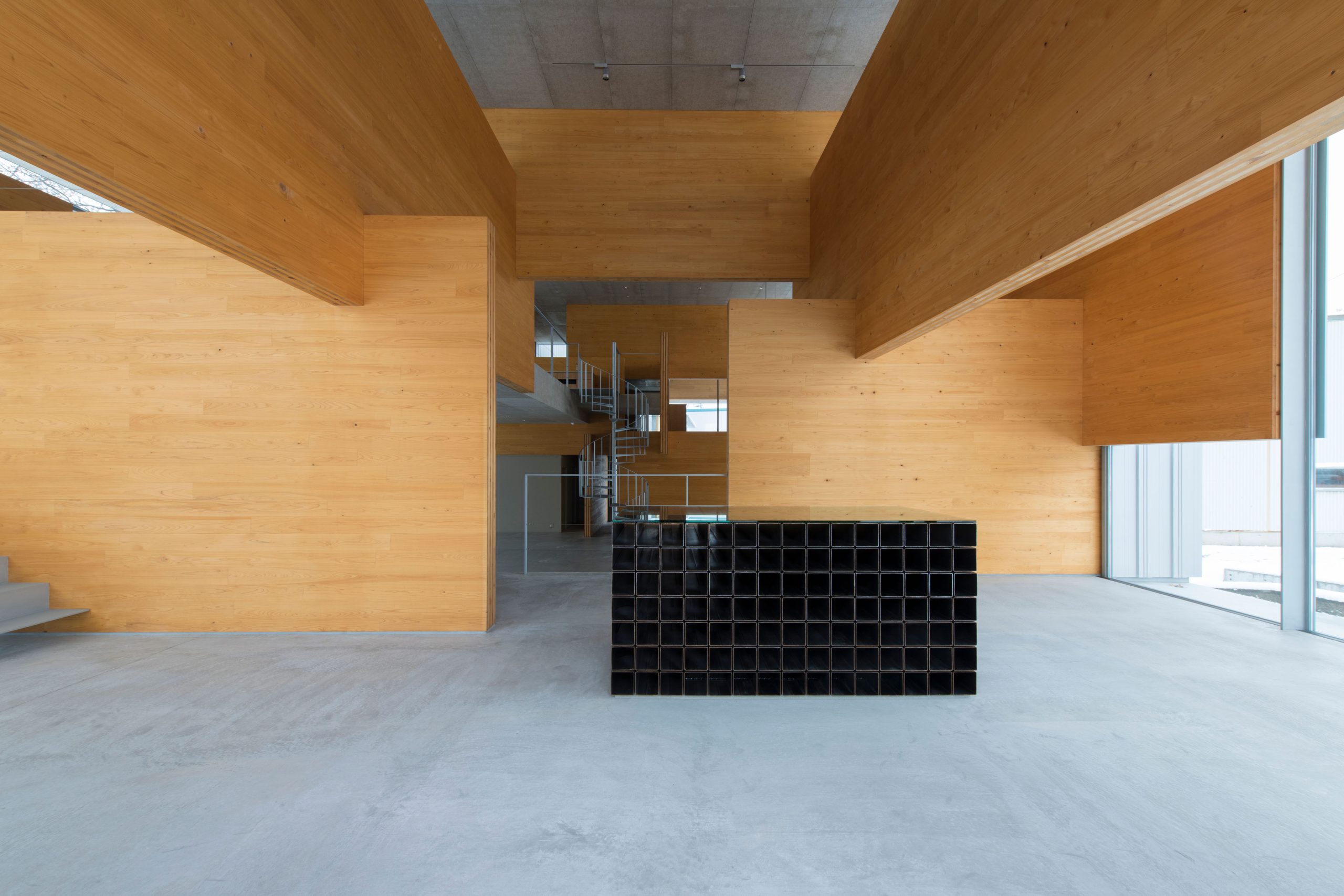
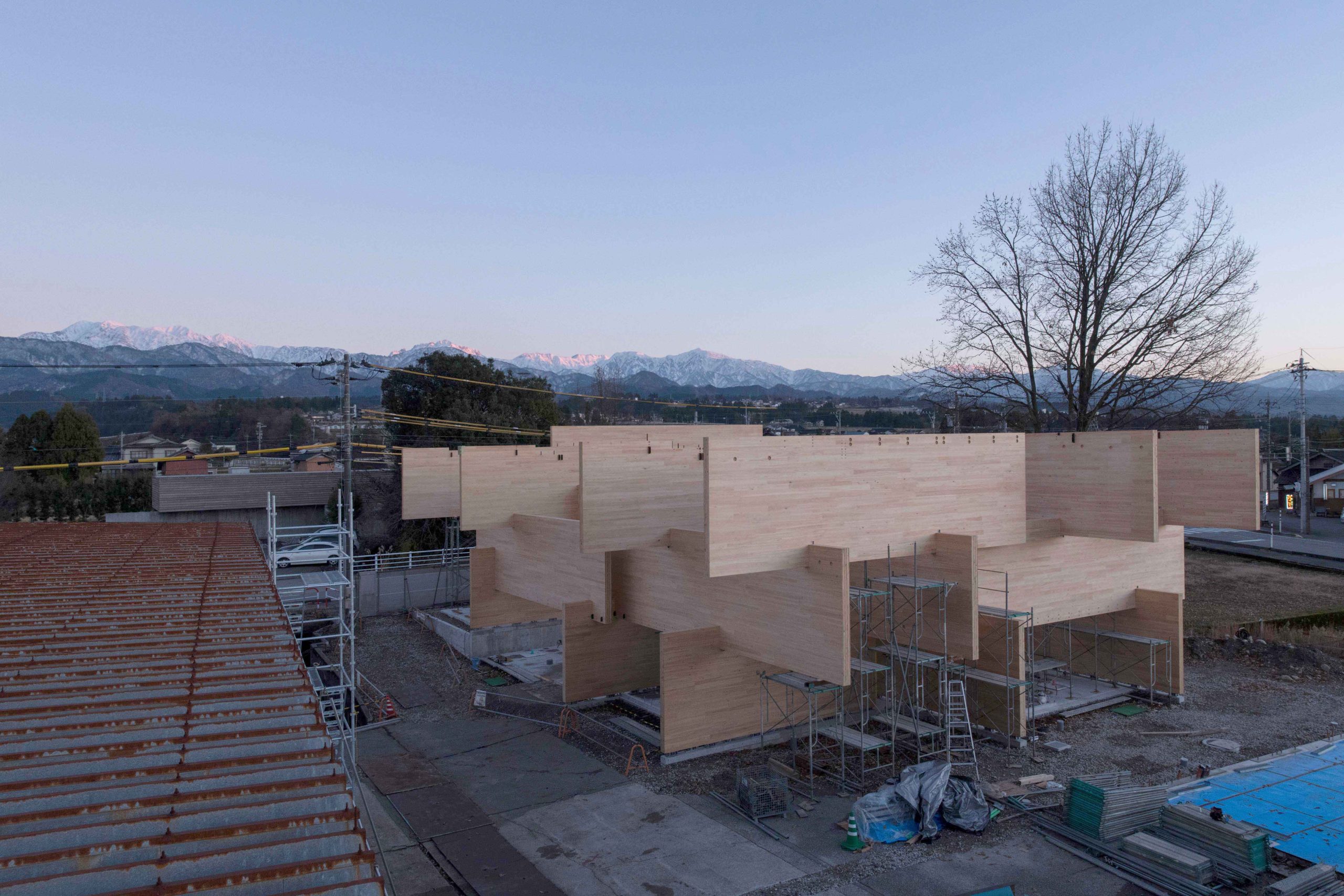
In terms of design, the CLTs in the interior spaces are finished in exposed structures, and connectors and machined holes are not visible at all joints, including the notches in the legs of the CLTs. In order to achieve this design, both strength and design were considered when developing the connectors, and the visibility of the joints was verified in the BIM model prior to design and construction. The building is the culmination of past technologies, including the use of ready-made connectors for some wooden frameworks such as the roof and second floors beams to reduce costs, and the use of Stroog.LSB in areas where axial forces are high due to the region’s heavy snowfall.
Stroog Office
Architectural Design:MOUNT FUJI ARCHITECTS STUDIO
Structural Design:KMC Ken Kamachi
Structural BIM Model:Stroog Inc.
Precut:Stroog Inc.
Total Floor Area:499.64㎡
Floors:2 above ground
Structure:Wood(CLT)
Building Function:Office
Photography:Ryota Atarashi
Connectors Used
Node.HSS Beam end connector for small-scale structures
Node.Column Column head and foot connector

Node.Fastener Configurable for other types of connectors and various fasteners
Node.HSML Beam end connector for mid to large-scale structures
Node.Rigid Rahmen joint connector
Node.S Connector that joins timber with steel
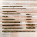
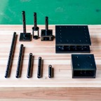
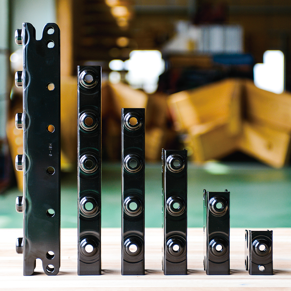
Stroog.LSB Various types of lag screw bolts
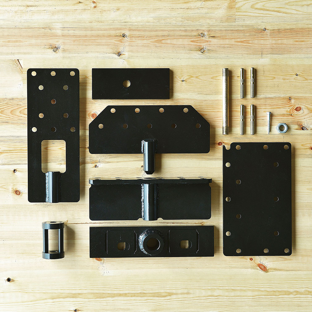
CLT Connector
Services Used
Stroog.test Strength testing services